tipsy.bot Part 4 - State Estimation
Tipsy Write-up Navigation Previous: IMU Next: Control
NOTE: The majority of the theory for the state estimate and PID controller was inspired by and heavily adapted from Brian Dwyer’s excellent write up on the subject. You can read about it here.
State Estimation
State estimation for Tipsy was conducted using a complementary filter which is a simplified sensor fusion schema that fuses noisy accelerometer data with gyroscope data (which has a tendency to drift).
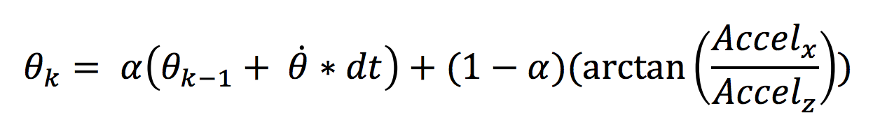
Complementary filter equation
The whole state estimate/controller system is psuedo-discretized using time step (k) size dt = 10ms (implemented using a 10ms delay
in the mainline code). The IMU data for the Z, X accelerometers and My gyroscope is read by the PIC, then fused together
using the formula above. α is an empirically tuned coefficient that weights the accelerometer and gyroscope values. In my
code α = 0.99 which functionally threw out the accelerometer data but kept enough of it to stop the gyroscope from
drifting too much.
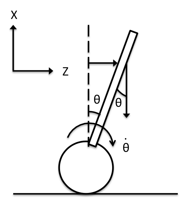
The accelerometer data was also used to check for a fall condition. If the accelerometer values were indicating that θ > 30°
or θ < -30°, the fall_condition bit would be toggled and conditionally prohibit the motor drivers from driving the wheels.
This was also visually indicated by a red status LED. This is shown in the gif below; when Tipsy is flat the wheels do not
turn and the red “fall condition” LED is on. As she is rotated to the approximate θ threshold the LED turns off and the wheels
begin to turn. This was convenient for verification of the IMU as well as making sure she didn’t drive off randomly.