tipsy.bot Part 2 - Motor Driver
Tipsy Write-up Navigation Previous: Introduction Next: IMU
MOTOR DRIVER
In order for tipsy to not fall over, I will be using two servo motors at the bottom to counteract any rotation when the controller detects a “falling motion” (aka a deviation from vertical). I will be driving them via the Sparkfun Dual TB6612FNG Motor Driver.
The big picture way that I will drive the motors is by defining a function that uses a timer with an interrupt to control the PWM signal. When the timer on the MPU raises an interrupt flag, it will complete the following code.
|
|
Motor_PMW_cnt is the value that increments up each time the timer interrupt flag is raised. It increments upwards until it
becomes PWM_max, at which point the code checks the status of the PWM wave (high or low) via Motor_PWM_Status. It then sets
the new value of PWM_max to whatever the desired speed of the DC motor is, resets the counter, and changes the status of the PWM wave.
The code below shows how the code implements the speed and orientation variables to control the direction of the motors.
|
|
All above code can be found on the project github (some code may change over time as I’m doing this write up in realtime).
Now that a rough draft of the code has been written (it took me ~30 minutes to realize I needed to add INTCONbits.TMR0IF = 0; to clear the timer interrupt 🙃)
we can start debugging.

Logic analyzer and tipsy missing a wheel
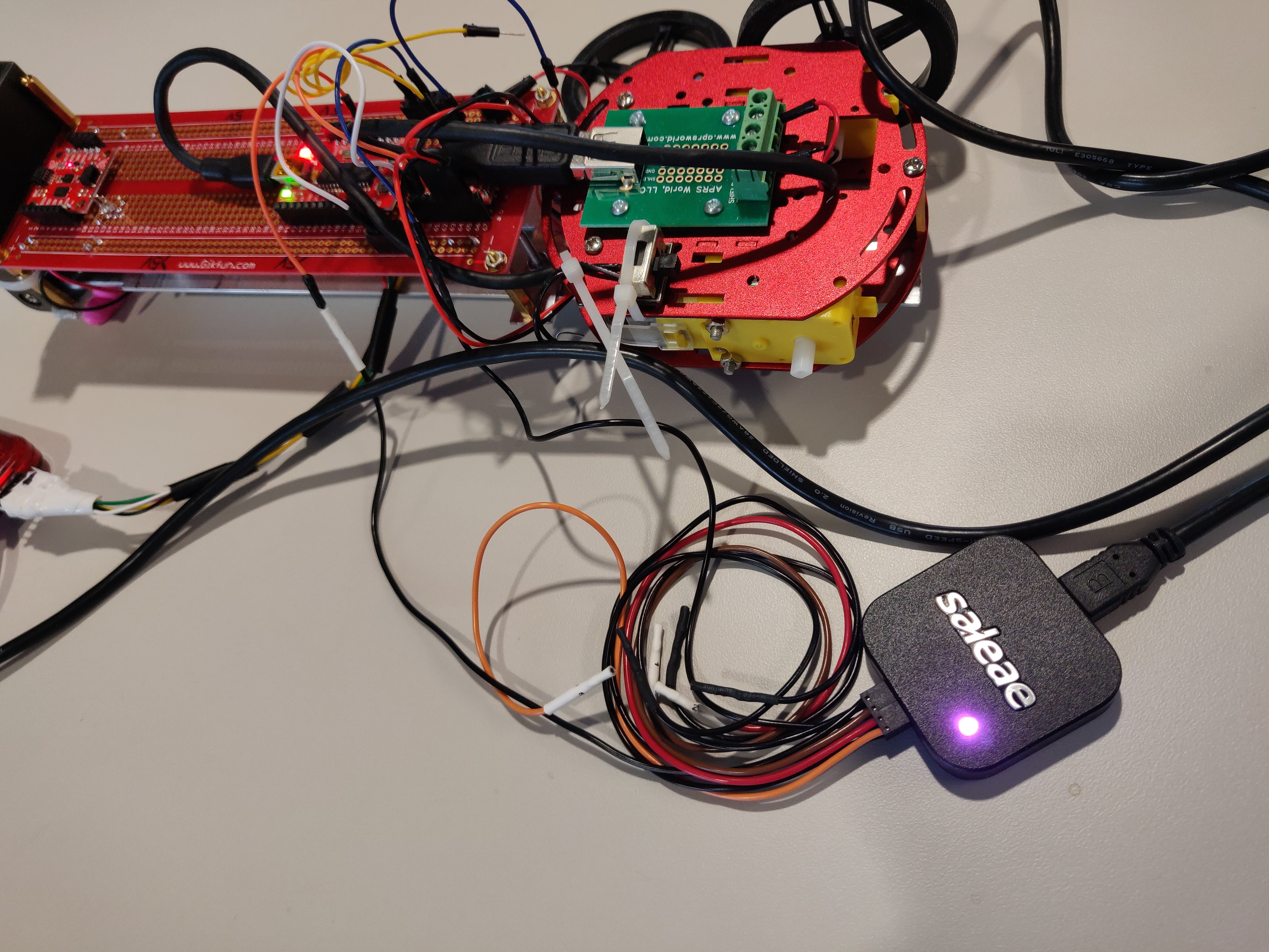
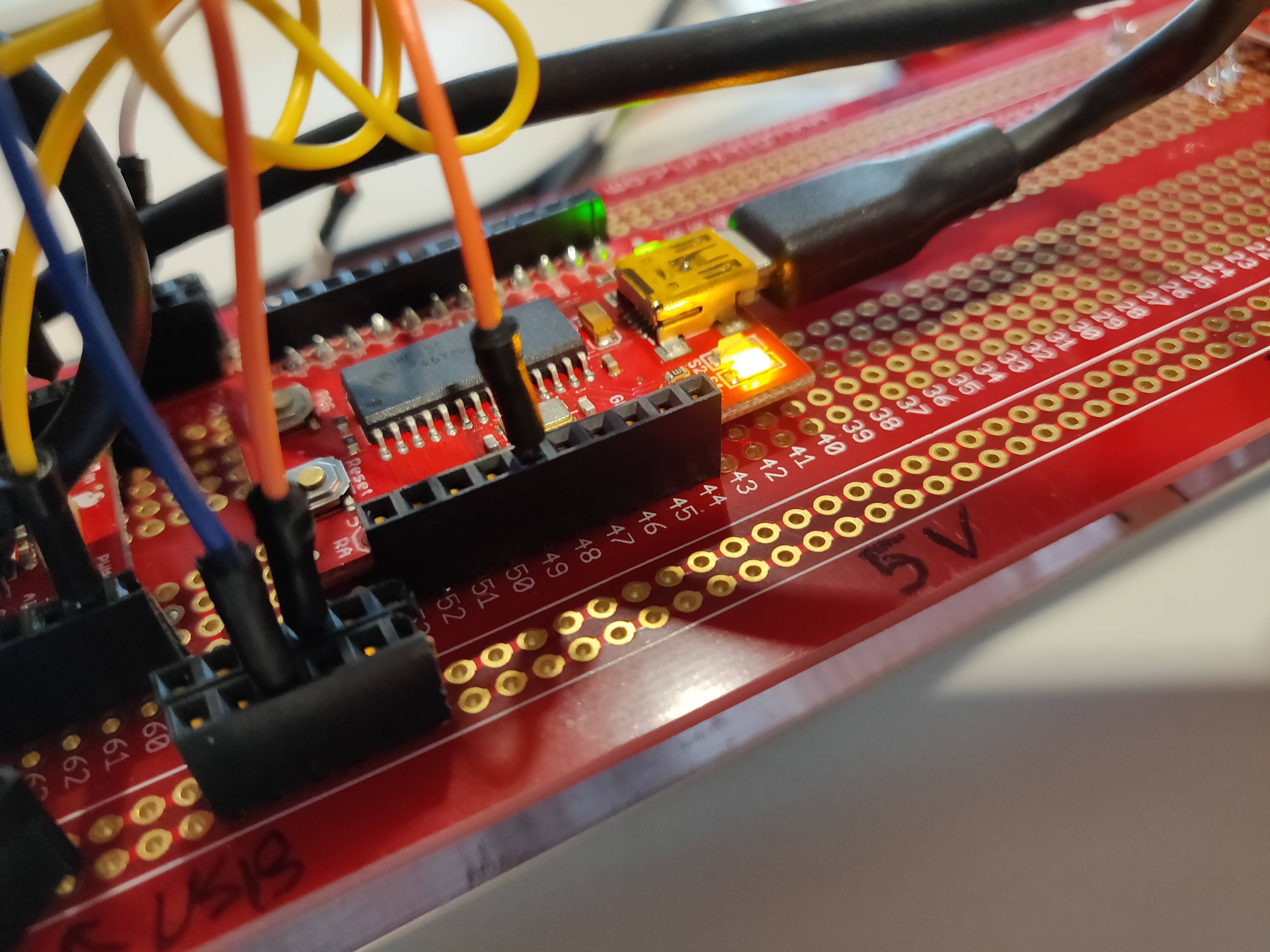
To debug my code I’m using a Saleae Logic4 logic analyzer which I’ve learned to love over the course of the semester. I’ve arbitrarily decided pin RA3 will be my PWM output so I’ve hooked the logic analyzer to it and made checked out my code.

RA3 pin for PWM output

Logic levels for PWM wave
As you can see in the output from the logic analyzer, at a full duty cycle is almost 3 seconds long which is much longer than
I’d like for my PWM wave. To adjust this, I need to adjust the value of PWM_max. Initially I was using a value of 0-65535 for
my maximum motor speed which ended up being too large of a value and created a huge duty cycle. To combat this, I’ve changed my max
value to 255 and adjusted accordingly. The resulting duty cycle is much tighter.

Much tighter logic levels for PWM wave

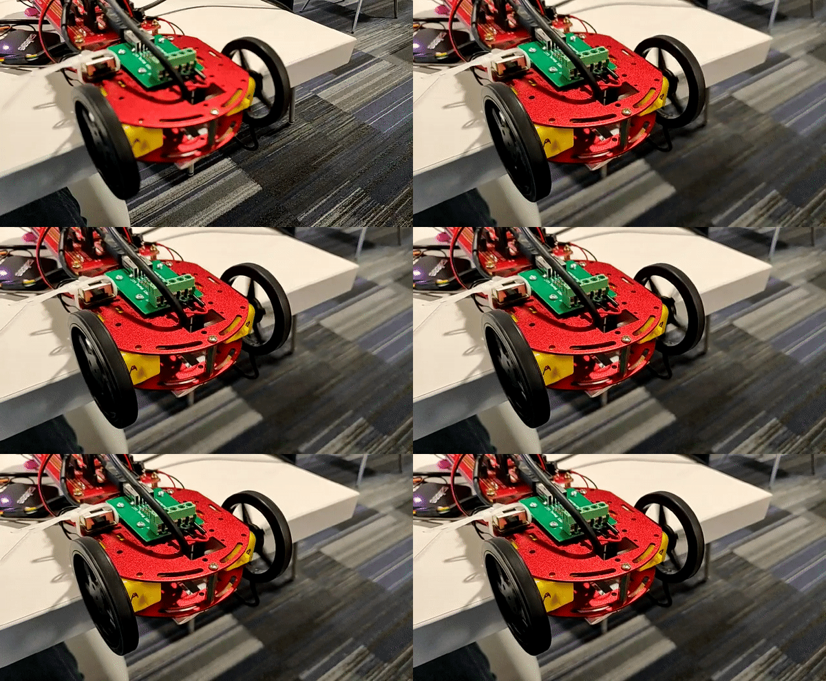
Voilà - Rotating wheels