tipsy.bot Part 1 - Introduction
Tipsy Write-up Navigation Next: Motor Driver
MOTIVATION
During the (current) Fall 2019 semester of my masters I am taking a class in embedded systems. Our class is working with the PIC18F87K22 microcontroller and doing a variety of low level things using mostly assembly code. For the class we have to come up with a final project involving an 8-bit PIC microcontroller.
During the first midterm of my estimation course, we had an exercise involving modeling the dynamics of an inverted pendulum. While procrastinating during the take estimation home exam, I googled videos of this and realized that this concept was not relegated to segways and I decided to attempt to build one using a microcontroller.
Hence “tipsy.bot” was born:
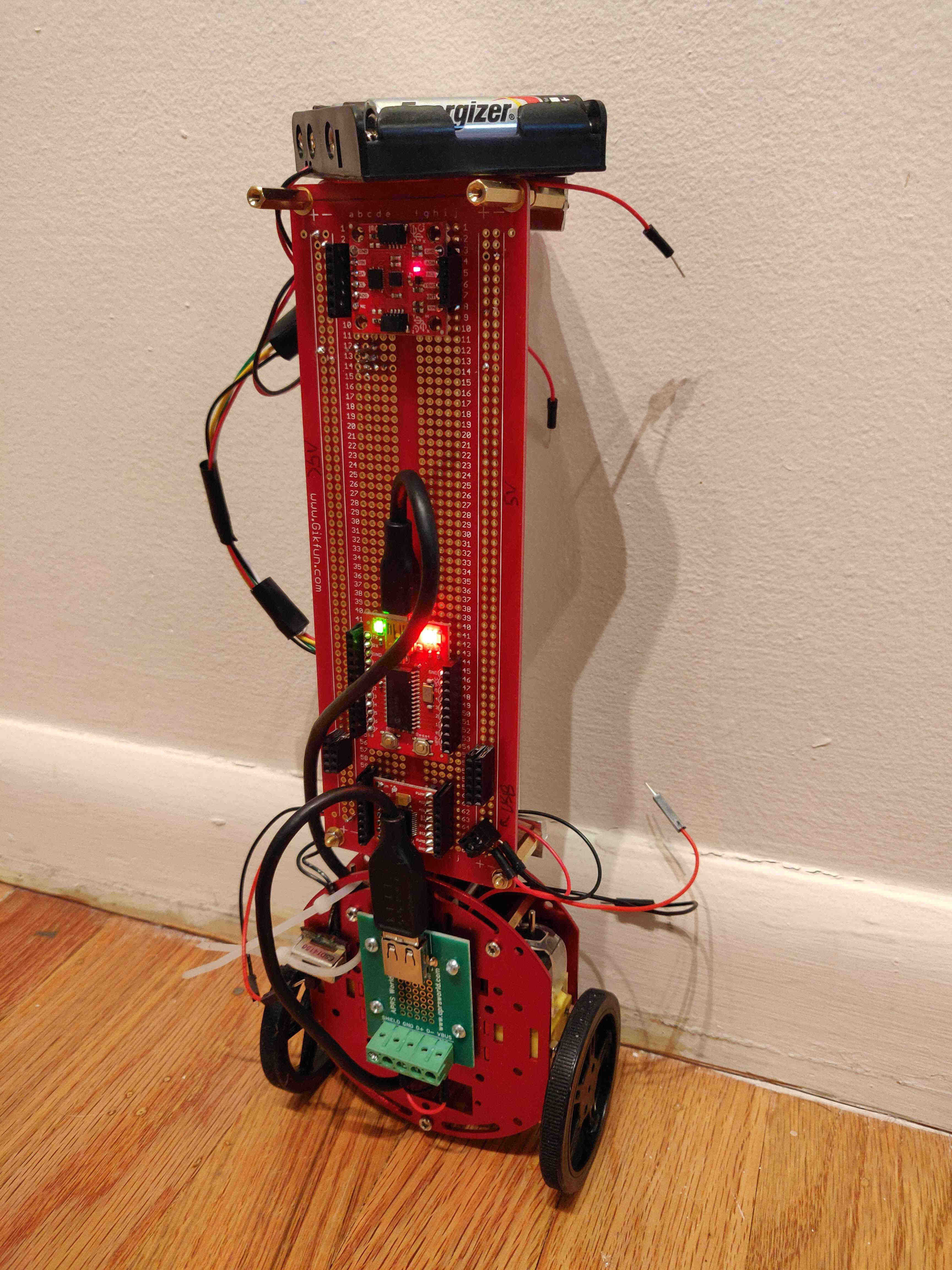
Early tipsy.bot chassis standing up semi-autonomously (e.g. leaning against the wall)
CHASSIS
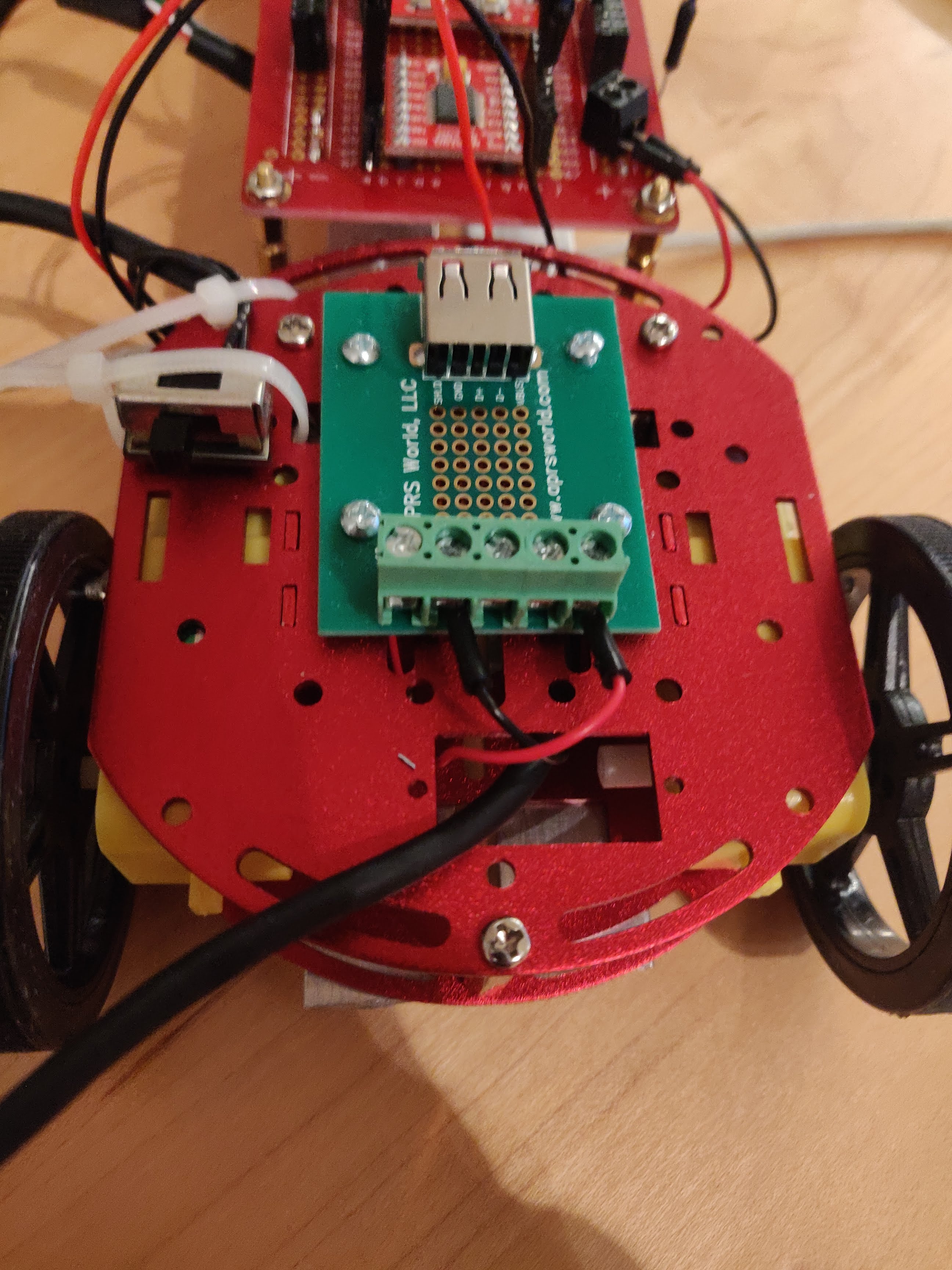
The lower (red) portion of the chassis was purchased from Sparkfun because it is compatible with the DC motors which would have otherwise been difficult to securely mount. These circular pieces of aluminum also have ample openings to accept additional hardware.
Aluminum motor mount
The “spine” portion of the chassis are two 3⁄4” x 1⁄2” x 1⁄16” pieces of aluminium angle that provide rigidity. Additional 1⁄2” x 1⁄16” pieces of aluminum flat bar are fastened to the angles to match the width of the breadboard and to accept the mounting hardware. The two angles are attached to the aluminum motor mounts with threaded hardware.
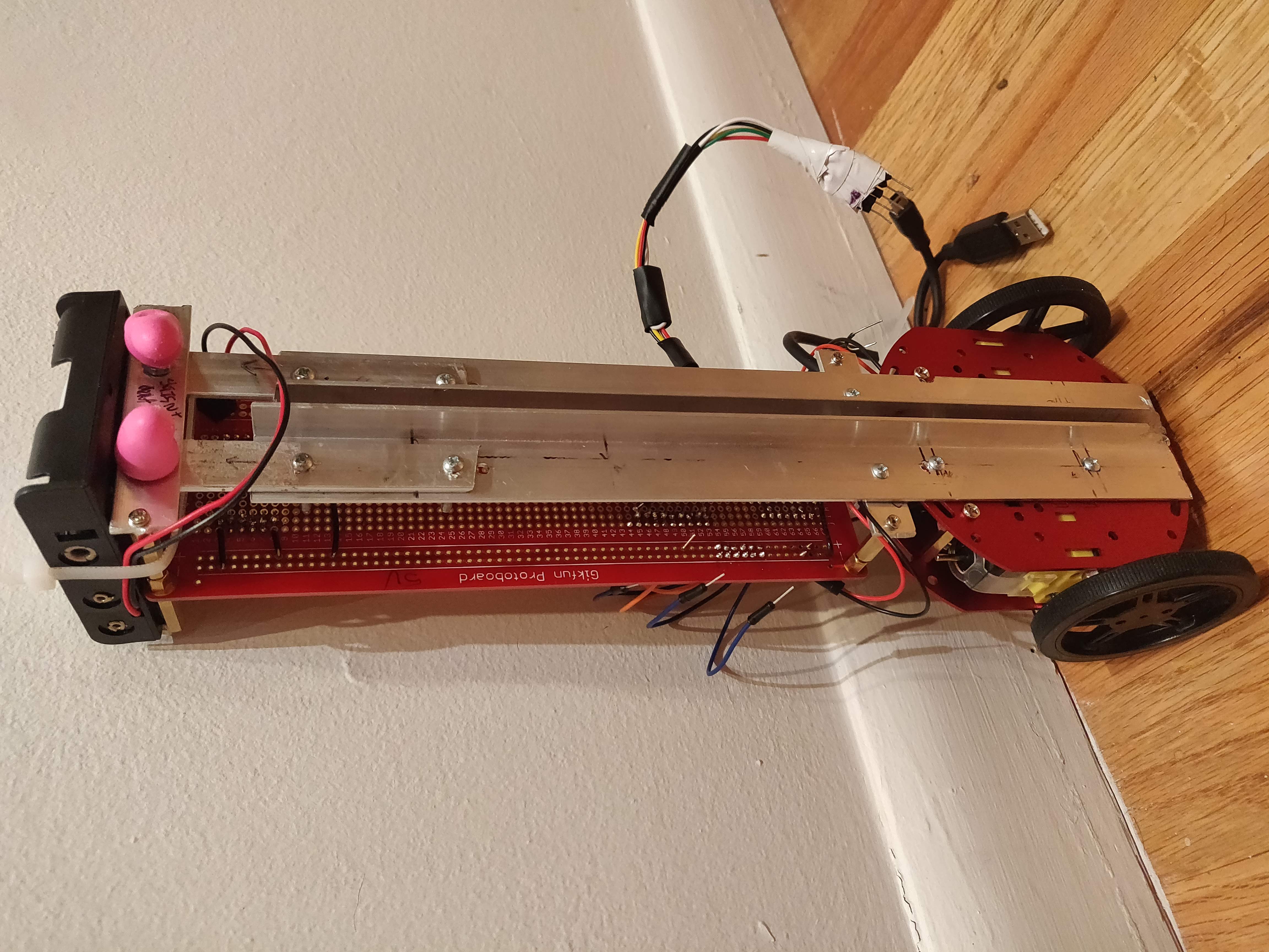
full view of spine
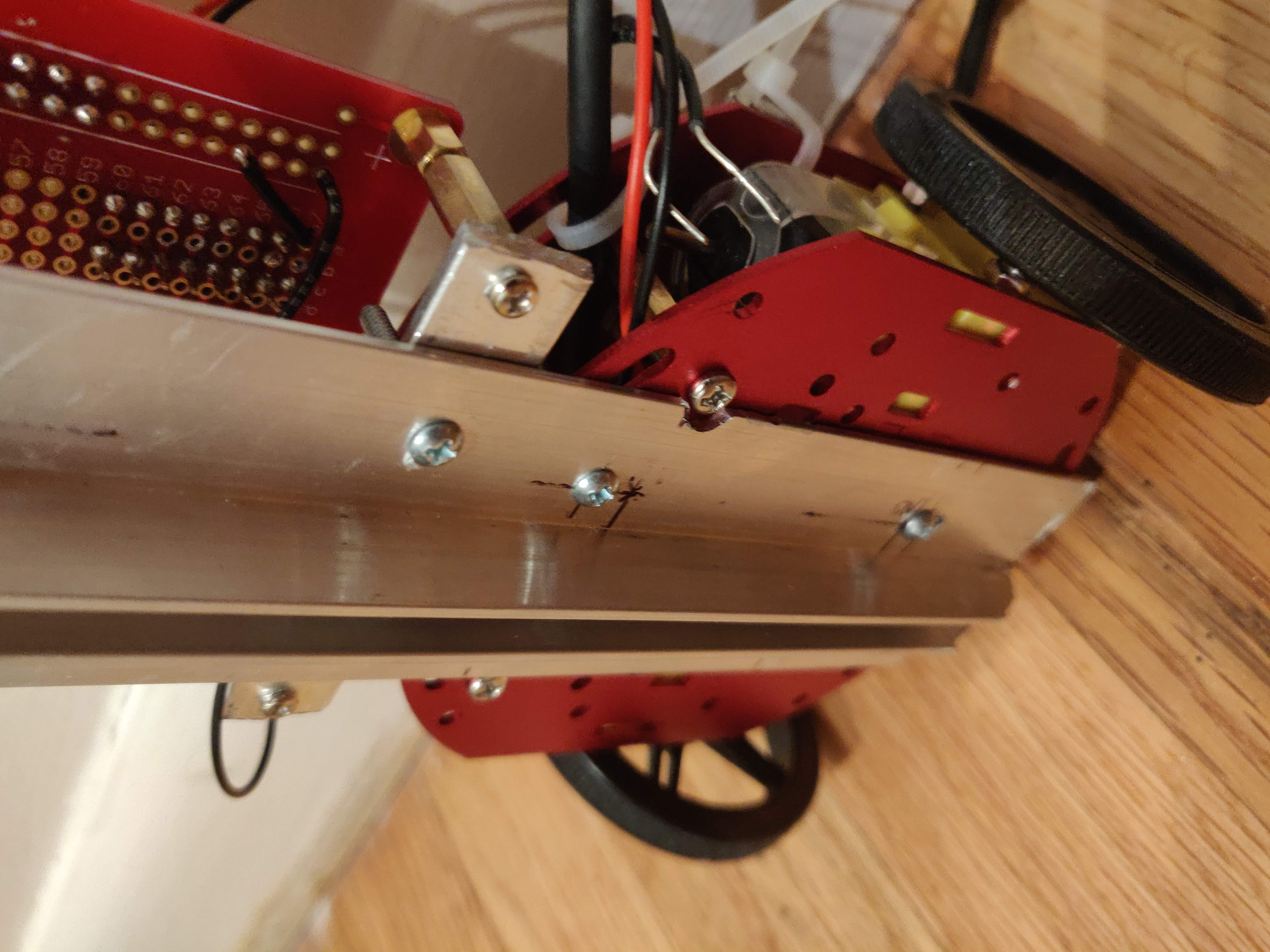
Connection of angle spine to aluminum motor mount
Detail of flat plate to angle attachment
HARDWARE
The three primary hardware components on the board are motor driver, MPU, and the IMU. These are shown in the picture below.
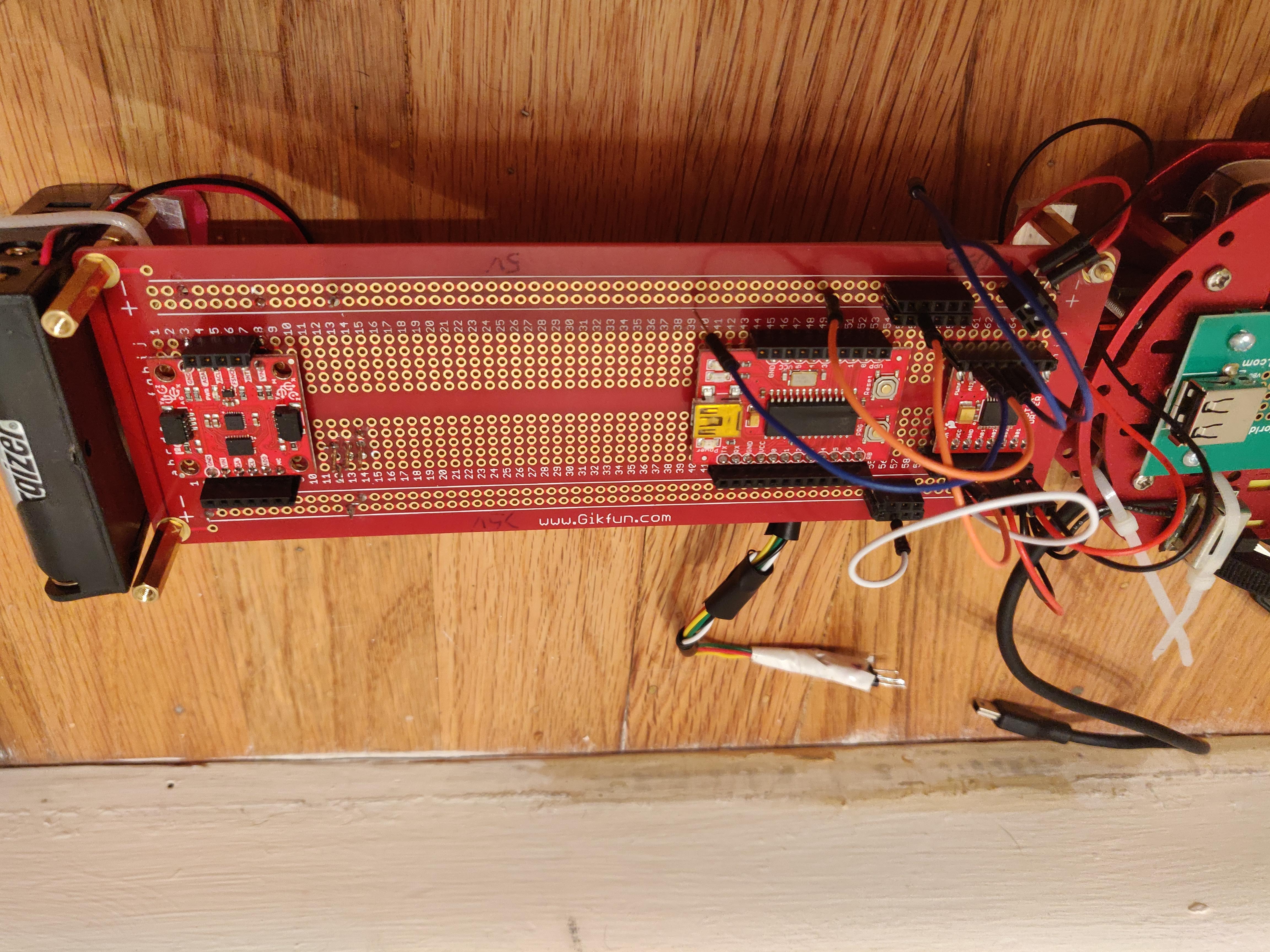
IMU (left), MPU (middle), Motor Driver (right)
I’ve chosen to put the battery pack at the top to start with. Although it seems counterintuitive, many other blogs I’ve read recommended doing this. The rationale is similar to if you’ve ever balanced a broom vertically in the palm of you hand; it is much easier to balance if the weight of the broom head is at the top. I may reposition down the road.
An earlier prototype was using a solderless breadboard for prototyping but I was having some trouble with electrical shorts so I went ahead and soldered all components onto the board. Because my schematic is still evolving, I soldered a bunch of female headers onto the board so I can use jumper cables as I figure out how I want to wire the board.
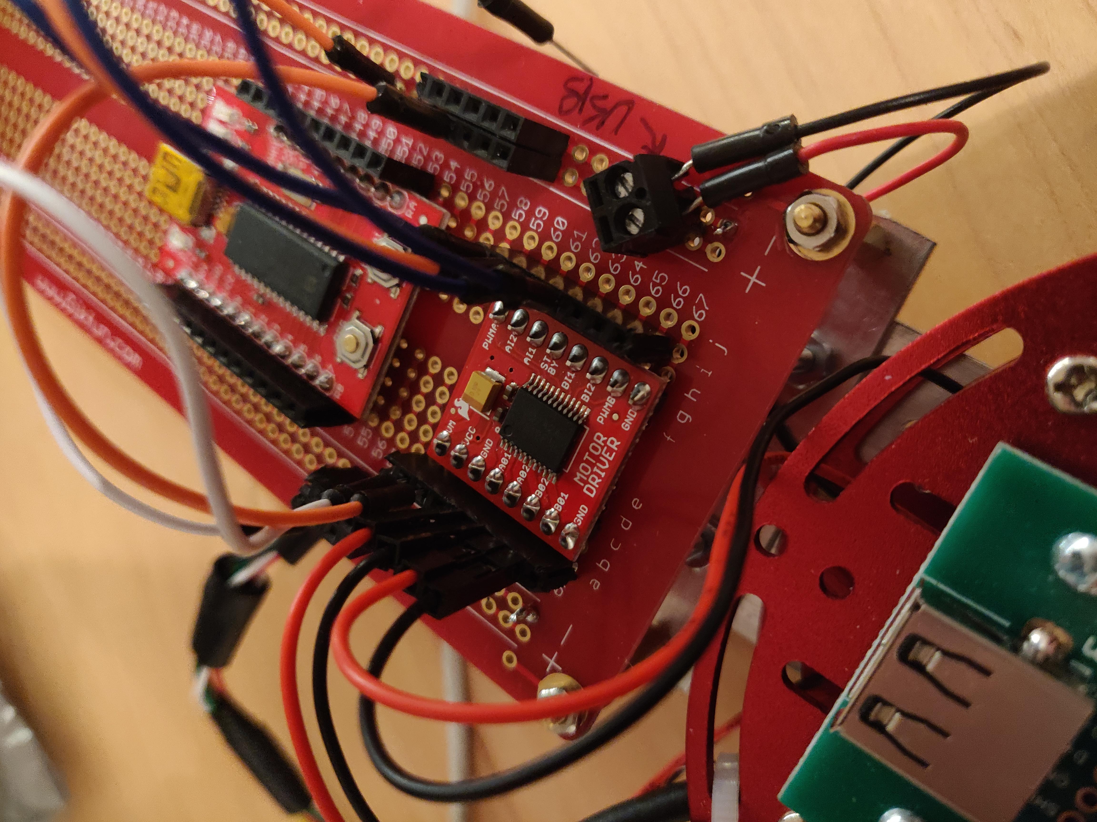
Close up of the motor driver with jumpers attached
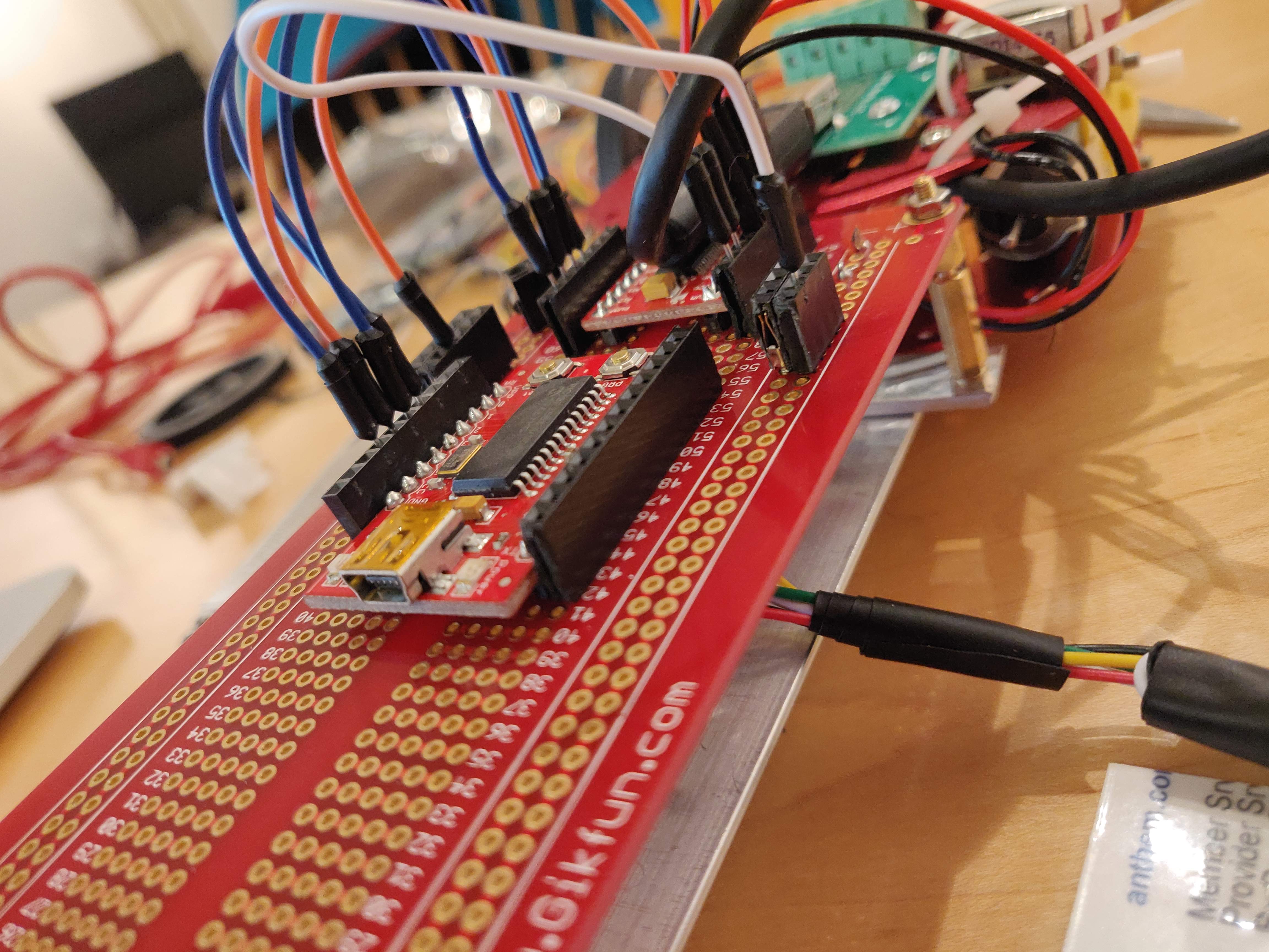
MPU with adjacent headers to allow for rapid prototyping with jumper cables
Programming the MPU requires the usage of an external programmer that interfaces with MPLAB via USB. I’m using the PICKit3 from Microchip. The PIC18F2553 requires certain pins to be connected to the appropriate port on the controller. This information can be found in the datasheet of the PIC18F2553 and the documentation for the board mine is mounted to. I created a handy schematic so I didn’t have to keep looking it up.
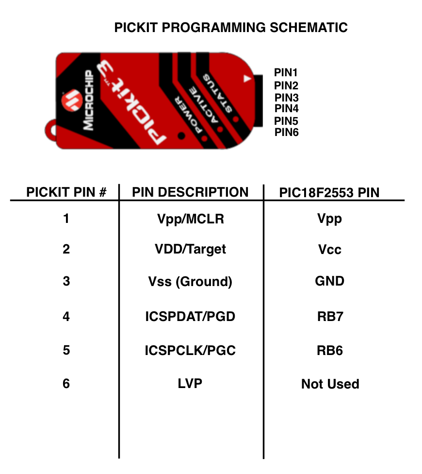
Programming schematic for PIC18F2553
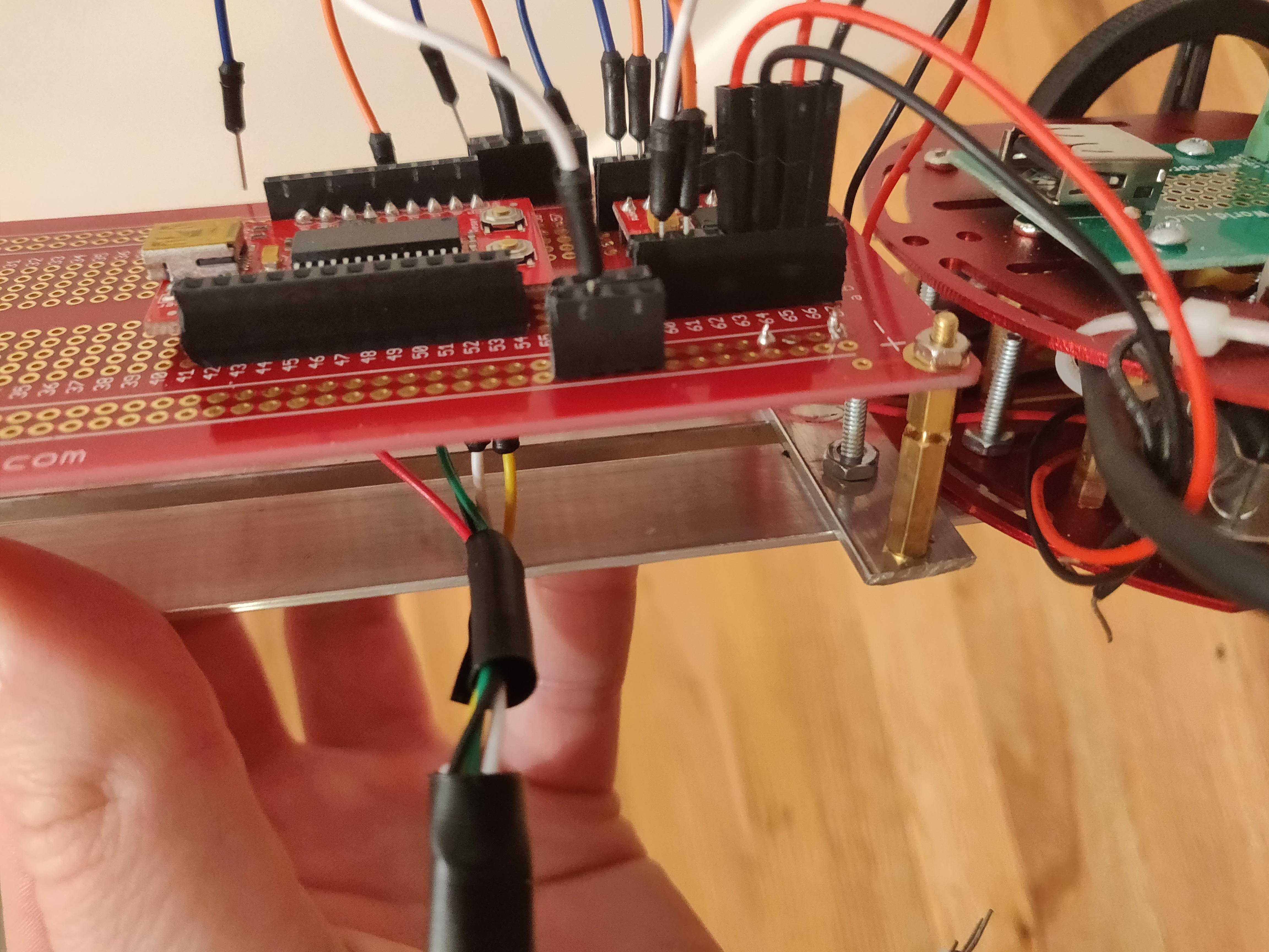
Furthermore, it got to be pretty annoying to constantly plug in and unplug the leads to the board per the schematic so I soldered in permanent programming lines which form a “rat tail” that allows for much simpler programming.
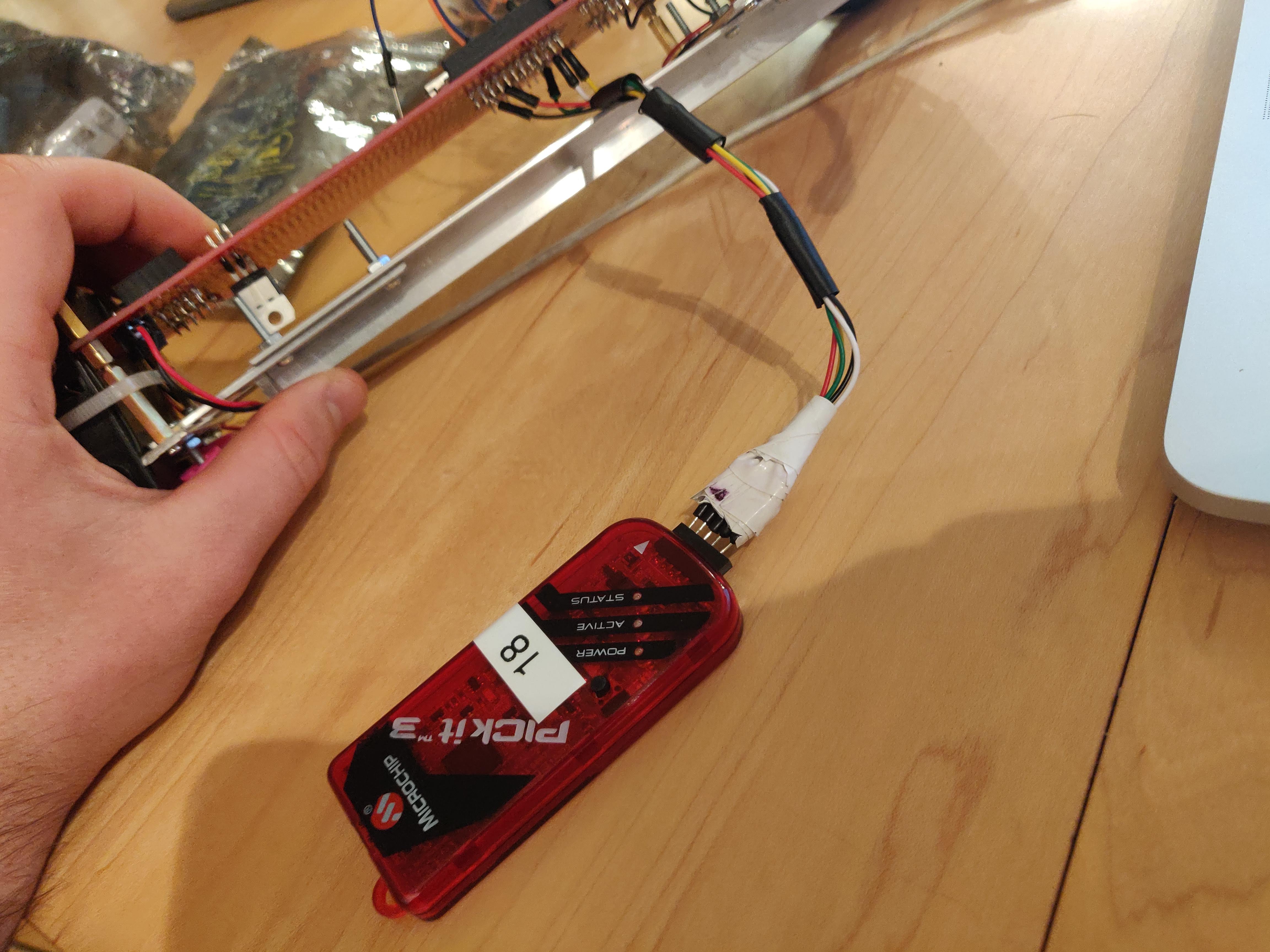
Dedicated programming line
Note that through some trial and error I discovered that there was some electrical interference coming in on the RB6/RB7 pins connected to the rat tail. Basically whenever I would try to drive the motors, the motors would behave like there was some sort of short in the system until I touched the RB6 connection on the rat tail. Through trial and error I think I was able to eliminate the error by setting the RB6/RB7 pins as outputs through the following code:
|
|