Elvira Part 2 - Motor Driver
Elvira Write-up Navigation Previous: Introduction Next: Object Detection
Elvira uses I2C to communicate between the Arduino and a PCA9685 controller chip to address the 12 servo motors that control her motion. Elvira’s motor driver code consists of several levels of abstraction from the low level serial communication (level of abstraction indicated by parenthesis)
Motor Control (Low)
Limb Control
Motion Control (High)
The motor and limb control layers of abstraction exist in the MotorDriver/src/Elvira.cpp file. The motion control layer exists in MotorDriver/MotorDriver.ino. I chose to implement the highest abstracted level within the Arduino sketch to allow it (hopefully) to play nice with the Arduino as a ROS node.
Motor Control
Motor control is achieved by communicating with the PCA9685 controller via I2C serial communication. I used an Artemis Thing Plus from Sparkfun - in retrospect I wish that I had used a more standard Arduino platform. The Thing Plus is fine in general but I’ve had to jump through some weird hoops because it is a relatively new offering. I2C communication is handled via the “Wire” library that is standard for Arduinos - Sparkfun did a good job at releasing example code for the Artemis and a lot of my I2C implementation is heavily inspired by theirs. For the artemis, I used pin16 for SDA and pin17 for SCL. This was connected to a Pi-Ribbon adapter that plugged into the provided breakout board that came with the Adeept kit.
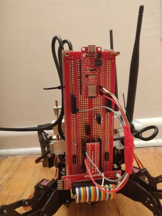
I2C connection detail
Motor control with via the PCA9685 is achieved by writing values to registers that correspond to the PWM duty cycle for a specific channel. Certain chip settings (eg duty cycle prescaling) exist within setting registers. The typical I2C write process involves three write operations:
1) Slave Device Address (PCA9685 is 0x40)
2) PCA9685 Register Address
3) Register Data Value
This is described in the data sheet:
Fig 20 from PCA9685 Datasheet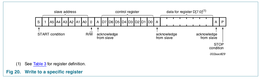
I began by defining a class for the PCA9685 with a “driver write” method that follows the write process:
|
|
Using this, we can initialize the PCA9685 by setting the prescaler to the appropriate value. The prescale value is based on the servo motor datasheet (MG90S) which requires a 20Hz duty cycle for operation. The appropriate register address value were determined by equation in section 7.3.5 of the PCA9685 data sheet. This occurs on the instantiation of the PCA9685 class.
|
|
Now that we have the ability to communicate with the PCA9685, we can address specific registers to set the required duty cycle to achieve the appropriate servo motion. Table 6 in the PCA9685 datasheet lists all the registers for PWM control (labeled as LED’s; this was originally designed to drive LEDs). Setting the specific PWM duty cycle for a given pin requires writing to four registers:
LED[n]_ON_L
LED[n]_ON_H
LED[n]_OFF_L
LED[n]_OFF_H
Note that [n] indicates the motor number which is used in the limb control abstraction layer. Each of these registers is 8-bits wide, however for the “_H” registers, only bits 0-3 contribute to the writeable PWM resolution. (Bit 4 will fully toggle the PWM on or off and bits 5-7 are reserved). This gives us a total of 12-bits of resolution when generating our PWM signals or a range of 0-4095. By writing values within this range into the on/off registers we can create a duty cycle that drives the servo.
The MG90S takes values between a 5-10% duty cycle at 50Hz which corresponds to a range of 1-2ms/20ms. 5% duty cycle corresponds to -90º and 10% duty cycle corresponds to +90º of rotation.
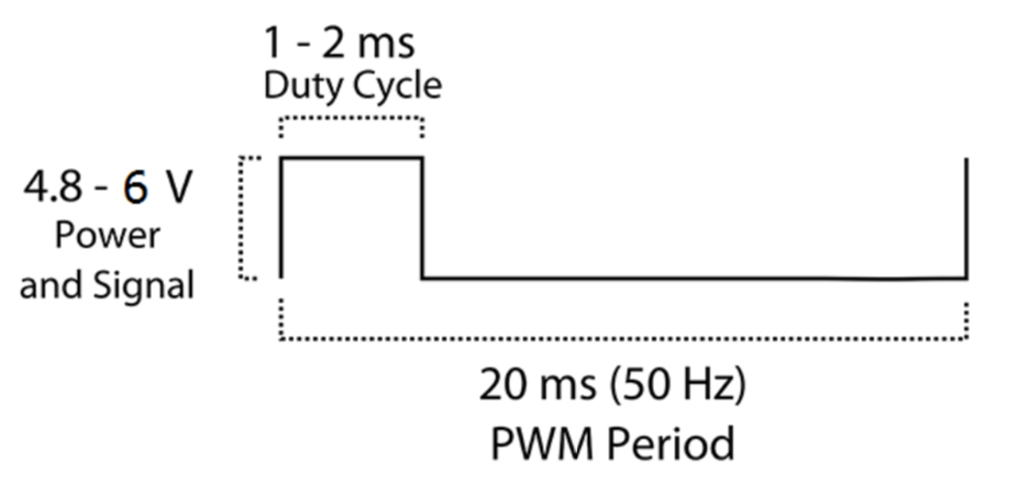
Per the MG90S datasheet
Limb Control
Elvira has four identical legs with a ‘shoulder’ joint and two ‘elbow’ joints (top and bottom). In total there are 12 servos that control all articulation. Servos were place according to the Adeept assembly instructions and labeled for convenience.
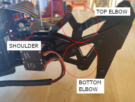
Detail of Elvira’s Leg
I created the following servo map schematics that I include in the .ino file:
/*   ASCII Schematic (Plan View, numbers indicate leg #)
 *        1  F   2     z
 *         \ * /       |_ x
 *          [ ]
 *         /   \
 *        3     4
 *
 *  ASCII Schematic (Section View, from back)
 *
 *        /\[ ]/\      y
 *       /       \     |_ x
 *
 *  Servo Map
 *  LEG | Shoulder, Top, Bottom
 *  1   | 0, 2, 1
 *  2   | 6, 8, 7
 *  3   | 3, 5, 4
 *  4   | 9, 11, 10
 */
The main goal of the limb control layer of abstraction was to be able to have control over individual servo motors without having to reference the schematic above. To accomplish this, I defined a class for each leg and provided it methods such as:
- “straighten” - drives both top and bottom elbow to +90º so the leg stands tall
- “sweep” - accepts an input value between 0 and 180 and controls shoulder articulation
- “articulate” - accepts two inputs (for top and bottom elbows) between 0-180 and articulates the elbow servos
In doing this, we only need to reference the schematic one time during the leg construction process by instantiating the Leg class as:
Leg leg1(0, 2, 1);
After doing this, we can call methods on each leg in a more human readable way such as
leg4.sweep(180);
I also created a “Body” class for Elvira. Because of her elbow joints, she has a small range of motion in the roll/pitch axes. The body class is only instantiated once (Elivra only has one body, ignoring any and all metaphysical implications in this assumption). This body class is similar to the limb abstractions, however in this case it is more convenient to just pass values for pitch and roll rather than try to control individual servos. Rotations are defined as follows (at this point Yaw has not been included). Note that the My, Mx, and Mz correspond to the axes shown in the ASCII schematic.
|
|
Motion Control
The final layer of abstraction exists in the arduino sketch. This is a series of several convenience functions that call the lower level limb/body classes and methods to achieve high level motion. Methods at this level include:
- “walk” - takes an input for the number of steps to walk forward
- “stanceReset” - straighten all legs and sweep legs back to a starting position
- “getShort” - articulate all legs to a “short position” so Elvira’s body squats down
At the time of writing this level of abstraction is still ongoing. I’ll probably do a separate post regarding walking because it turns out that figuring out a quadruped gait with sloppy servos is pretty difficult.
Design Thoughts
As with all designs, the introduction of new tools will bring both sweet features and painful “gotchas”. I think overall I am happy that I decided on using a microcontroller in conjunction with the Jetson, however I do have a few thoughts on this design decision:
Robustness
I think the biggest feature that the microcontroller brings is robustness for attachments. By having a relatively independent “dumb brain” (as opposed to the “smart brain” found in the Jetson), I can compartmentalize certain feature sets (mainly the motor driver) which I think makes for a tidier final product. It also allows for simpler expansion - I’m considering adding a small OLED screen to the assembly and I predict it will be easier to integrate that into the Arduino ecosystem and leave the Jetson for perception/planning only.
Speed
When I was considering using the GPIO functionality of the Jetson I did some back of the envelope benchmarking between that and an arduino. This ultimately informed my decision to go with an arduino for low level motor control. In retrospect, since any peripheral communication is happening via I2C, I wouldn’t have been able to access the full clock speed of the microcontroller and thus could have gotten away using the GPIO functionality of the Jetson. That being said, although I did add some complexity to the project, I think the added robustness and ability to dive deeper into ROS made it worthwhile.
My benchmarking was very simple - just toggling pins over and over.
|
|
I used my Saleae Logic 8 logic analyzer to take a look at GPIO pin toggle speeds on the Jetson:
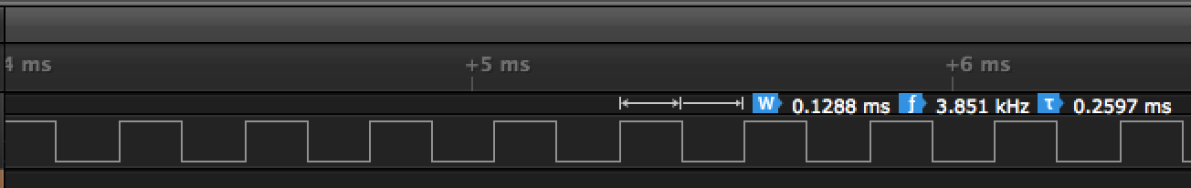
GPIO control on the Jetson is very slow
Obviously ~0.1ms is really slow for embedded applications so I decided I needed to go a different direction. Comparing this with the Arduino, I think I saw roughly an order of magnitude increase in pin toggle speed which is more in line with what I potentially need for any embedded systems.